Zaack’s DUST is a small sensor that lives inside industrial ventilation ducts. It measures how clogged they get optically: an infrared LED lights up a plate exposed to the airflow, a receiver reads the light coming back, and the more dust builds up on the plate, the more that light drops. From this attenuation, Zaack’s cloud derives the clogging level, sent over LoRa, and triggers the cleaning of a duct only when it actually needs it, instead of sending a technician on a fixed schedule. Zaack belongs to the Igienair group, whose business is precisely ventilation cleaning. The V1 had been in service since 2019. At Kickmaker, I was the technical lead and project manager for the V2: first understand why the V1 was going off the rails in the field, then evolve it without reinventing it.
a product in the field, defects coming back
The V1 worked, but the field kept reporting the same things. First, battery life: meant to last several years, it was dropping below one. The electrical design leaked currents, fatal on an IoT object that must sleep more than 99% of the time, and the batteries drained far too fast. Then the measurement itself: the dust estimate was very sensitive to humidity and temperature swings, which skewed the readings. On top of that, a battery gauge sending back inconsistent levels after a battery swap, LoRa disconnections caused by a poorly controlled internal antenna, key components going end-of-life or hard to source, and a production bench piling up issues, board retention, a flashing bug, no real electrical test, random rejects. A product to take over cleanly, rather than let drift.
the battery-gauge bug
Before redesigning anything, I ran the investigation on the most insidious defect, the false battery gauge. First reflex, rule out excess consumption: the current analyzer showed no difference between healthy and faulty boards. So the problem was in the voltage measurement chain, not in consumption.
I instrumented a board on the oscilloscope, swept a bench power supply across the full battery range, and compared the input and output of the op-amp follower that reads the voltage. The finding: at the top of the range, full batteries, the output dropped away from the input by more than 240 mV. Poorly made resistor solder joints made the picture worse, but they were not the root cause: even re-soldered, some boards stayed wrong.
The real cause: the chosen op-amp was not rail-to-rail. Its manufacturer only guarantees linear behavior up to about 1.2 V below its supply voltage. Beyond that, the output becomes unpredictable, exactly where the full-battery voltage landed. To stay in the guaranteed zone, you would have had to sacrifice half the measurement range.
The fix I recommended is the kind I like: a rail-to-rail op-amp, same package, same pinout, equivalent price. A drop-in replacement, no PCB change, that restores the full measurement range and makes the behavior predictable again. Change a component, not the board.
evolve rather than rebuild
These diagnoses drove the V2. The trap, on a product already in the field, is wanting to redo everything. I took the opposite path: keep the V1’s mechanical enclosure and board dimensions, and focus the changes where field returns and sourcing justified them. A targeted evolution, not a clean break. The product stays compatible with its installation and its manufacturing chain, and every change answers a named problem.
what changes, from analog to digital
The dust sensor first. The V1 read the attenuation of infrared light with an LED, a photodiode and an analog amplifier: a chain that drifts with temperature and humidity, which had to be corrected afterward in the algorithm. The V2 moves to an all-in-one optical sensor, digital, with built-in thermal compensation, optimized LED control and a real sleep mode. The measurement becomes more stable against ambient conditions, and you gain on consumption.
The brain and the radio next. The V1 relied on a radio module that had become expensive and hard to source. The V2 replaces it with a microcontroller that integrates the compute core and the LoRa transmitter in a single package: cheaper, better available, a more compact design.
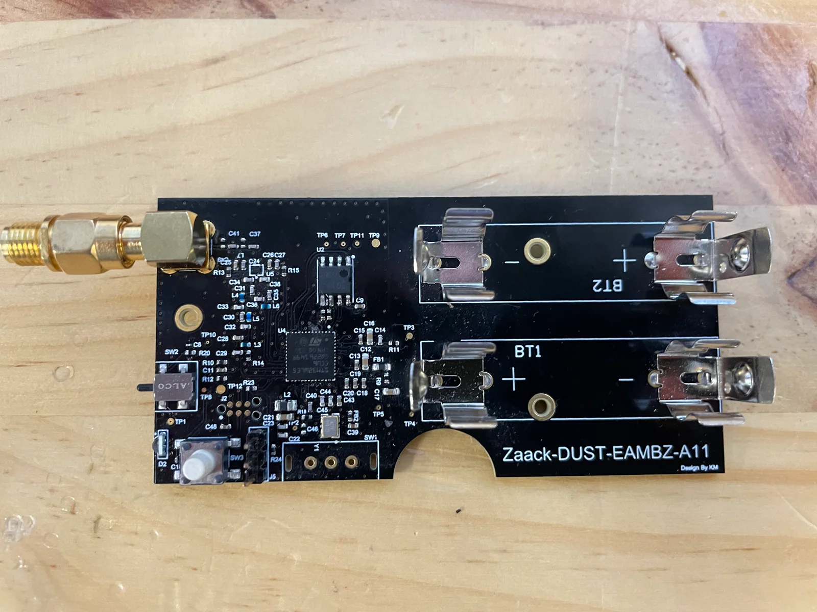
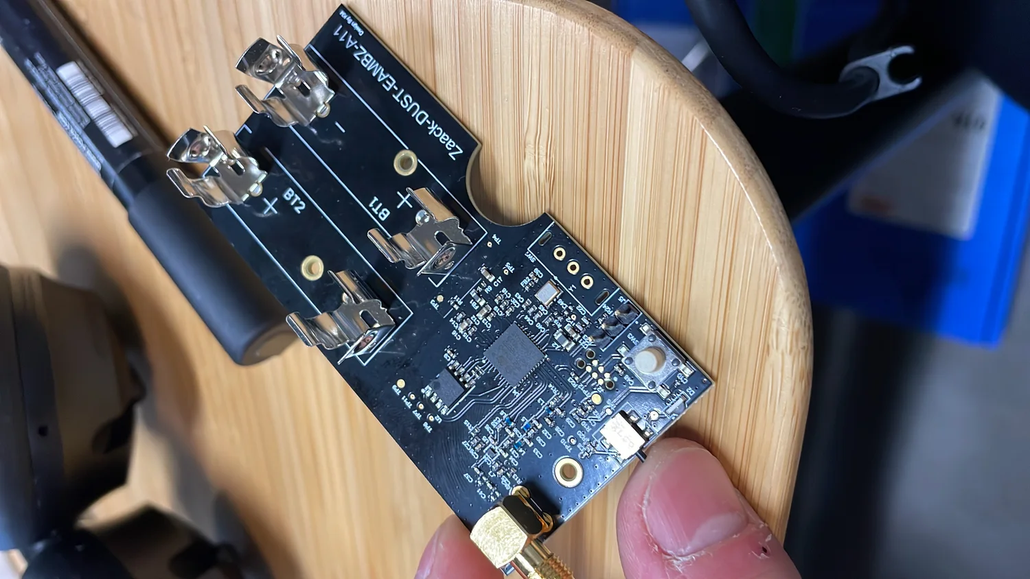
The antenna. The V1’s internal antenna caused the disconnections. The V2 moves to a steerable external antenna, with a 50 Ω matching network designed for both European and US LoRa frequencies. You can finally point the antenna at the gateway.
Power, last. The V1 carried three AAA batteries but only used part of their charge, because the electronics no longer worked below 3.3 V, and leakage currents finished off the battery life. The V2 moves to two AA batteries and a boost converter that makes 3.3 V even when the batteries are nearly empty. You actually drain the batteries, you hunt down the leaks that were killing the V1’s battery life, you cut cost and bill of materials, and you get back the four-plus years targeted instead of less than one.
from a mute product to one that talks
The V1 had almost no interface: no button, no LED, no debug port, no memory. At installation as at servicing, you worked blind. The V2 fixes that:
- a button that fires a LoRa test frame: the installer validates connectivity on the spot, without waiting for the next scheduled send;
- status LEDs that show the send and acknowledgment phases;
- a UART port and AT commands to test the board in production and read the product on a service return;
- an EEPROM that stores messages when the LoRa link drops, to resend them later.
Nothing spectacular on its own, but together it turns a passive object into a product you can install, test and troubleshoot.
built for installation and servicing
It was an explicit request from Zaack, and it lines up with the diagnosis: the V1 required fully dismantling the product for the slightest check. With the test-frame button, direct UART readout and AT commands, a technician validates or diagnoses the unit without removing it. On the factory side, the V2 comes with a production bench that really tests the boards and traces the sub-assemblies, serial number, firmware version, programming date, where the V1 just flashed and serialized.
bring-up, the real life of an EVT
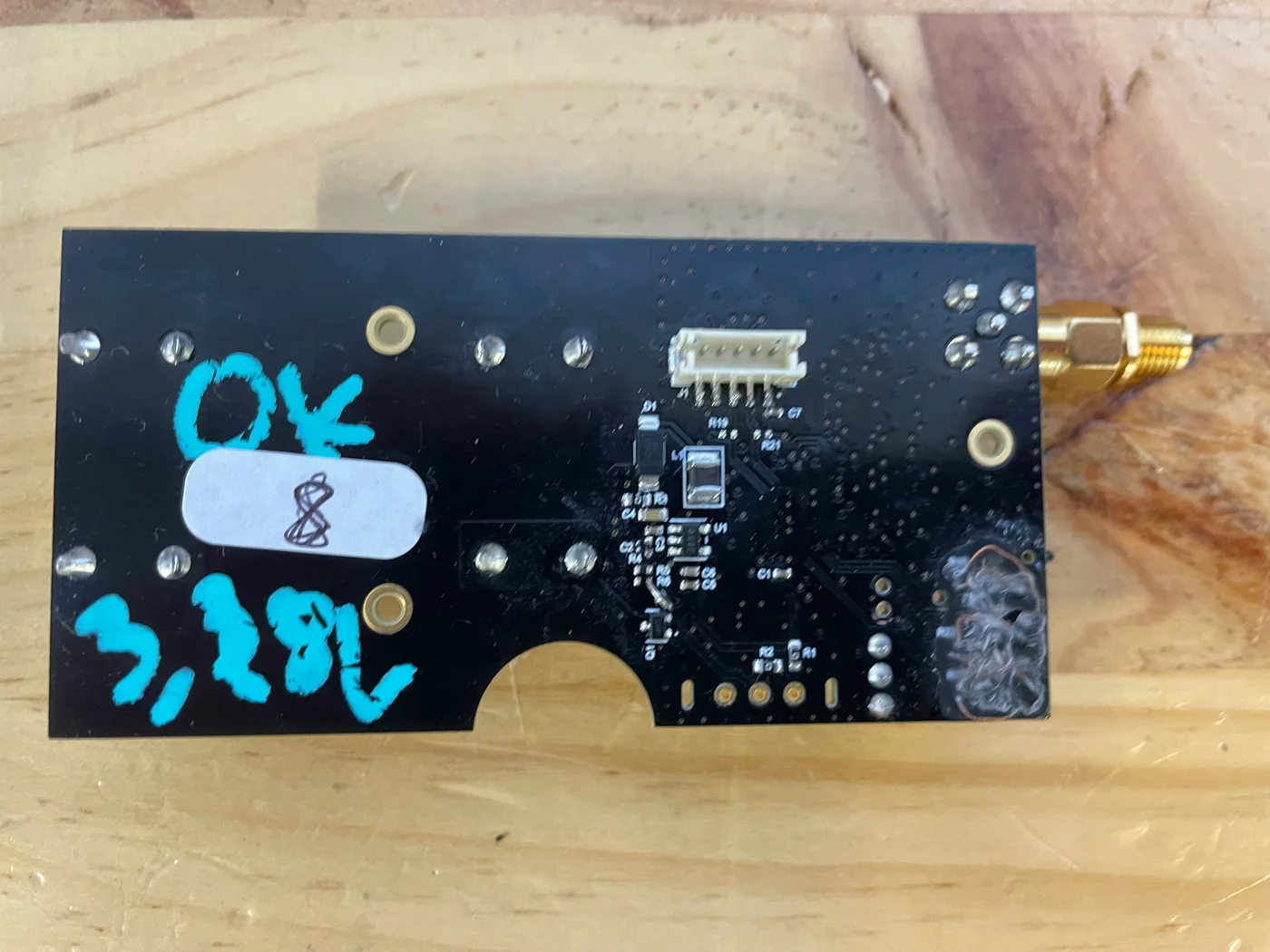
Between the schematic and a board that works, there is bring-up. I assembled, powered and sorted the first EVT1 boards one by one: converter output voltage checked, the famous 3.28 V noted in marker on the back of the boards, LEDs rewired by hand when the initial implementation was wrong, and a detail typical of these phases, a converter capacitor that absolutely must not be fitted, on pain of pushing up the idle consumption.
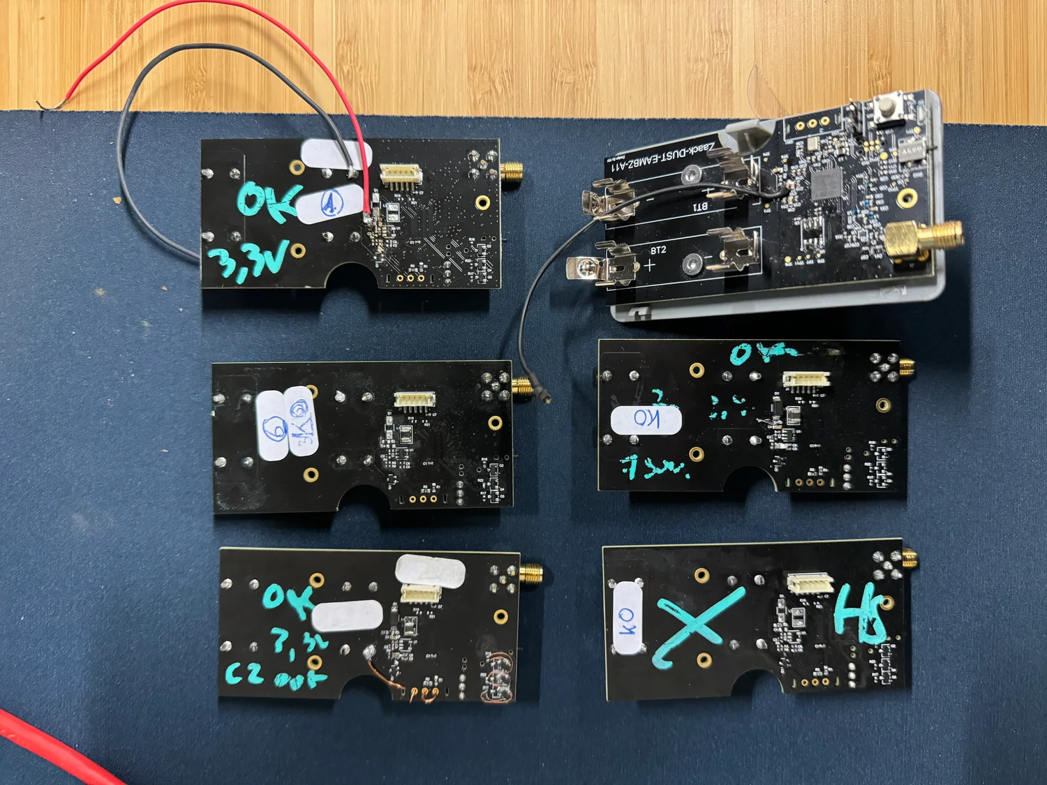
On the table, the boards marked “OK” and “KO” say it all: that’s where you turn a design on a screen into a product that holds up.
my role, what I take from it
On this project, I owned the service diagnosis, the V2 requirements spec, and the bring-up of the first boards. The lesson, I set it against other redesigns I’ve led: rebuilding everything is not always the right answer. On a product already installed at customers, a targeted evolution, guided by real field returns and by sourcing, beats a clean break. The finest fix of the project did not change a single line of the PCB: an op-amp in the same package, chosen for the right reason, and a gauge that reads true again. Modernizing, here, was not redoing everything: it was correcting what skewed the measurement and the battery life, and giving the product the means to get installed, tested and repaired.